As discussed in the Performance section of this manual, a polar diagram models all possible wind angles, even angles which are impossible for a vessel to sail.
The range of sailing angles a vessel can sail could be affected by many factors. Some of them are:
- the sea state
- the condition of the sails
- the condition of the crew
- is the vessel being steered by an alert crew member, a wind vane or an autopilot
There are many other factors which will determine the range of sailing angles you may want the solver to restrict itself to.
By setting these wind angles to something reasonable for your current conditions, the solver will be able to generate more realistic paths than it otherwise would be able to.
| Setting the sailing angles to reasonable values, given the conditions, for your route, is essential to having the solver generate results which will be useful for you. |
The upwind and downwind sailing limits can be specified as either a true wind angles or apparent wind angles.
How it works.
The solver generates new isochrones, one by one, based on the points present in the previous isochrone. For each point in an isochrone, the solver generates many headings, radiating in an outward direction. Given the true wind speed and direction at that position, the solver is able to determine the estimated boat speed from the provided polar diagram. Once the boat speed is known, the system can calculate the apparent wind angle.
Each heading that the solver has generated, for each point on the isochrone, has its angles tested against the limits you set. Only those headings which depart the point within the limits are accepted and allowed to be considered when building the next isochrone.
Examples.
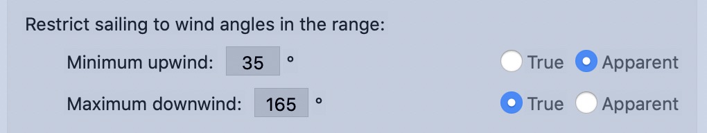
As all sailors will know, when beating into strong winds with a rough sea state, your tacking angles will be different than when sailing in calm seas.
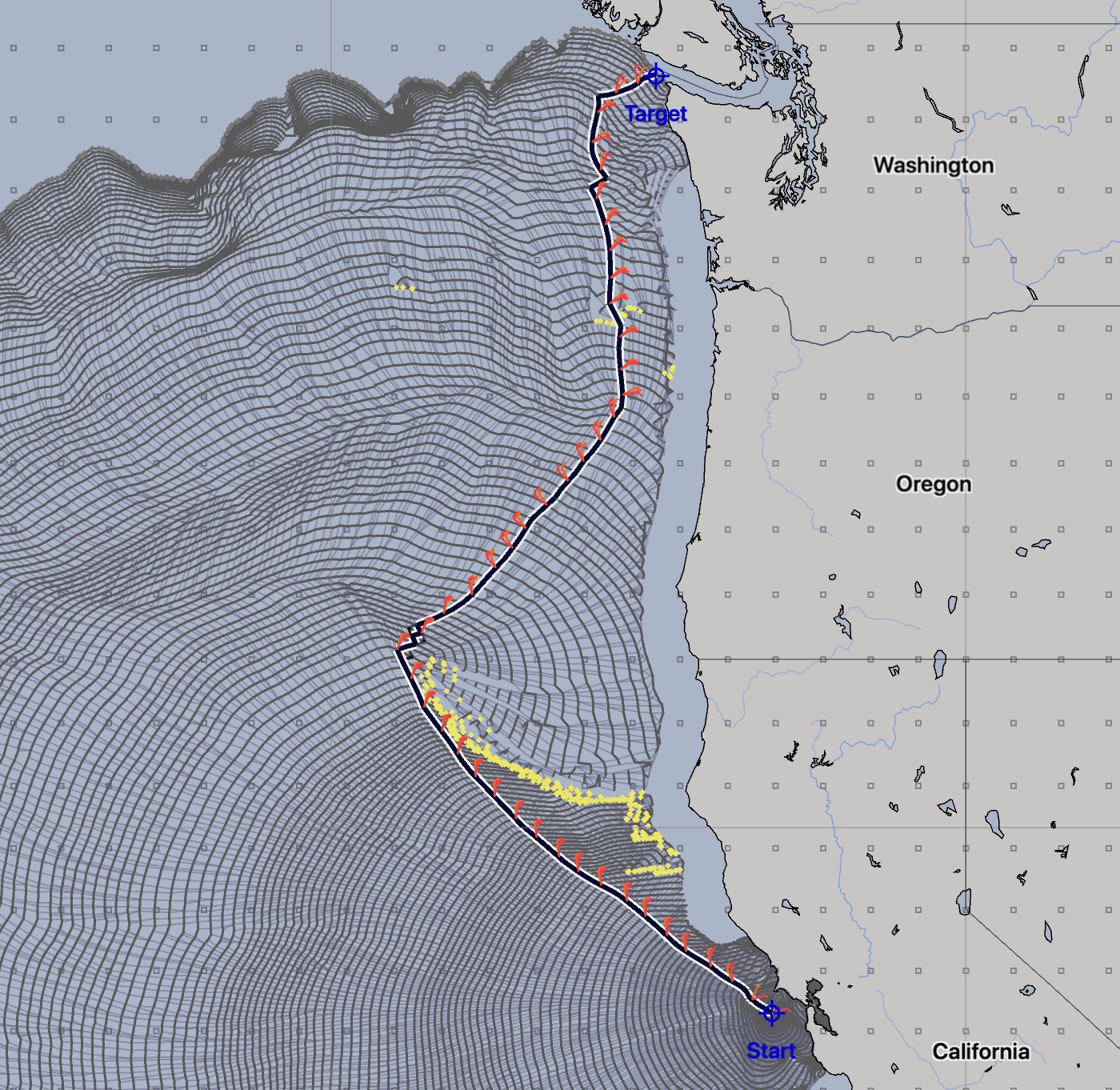
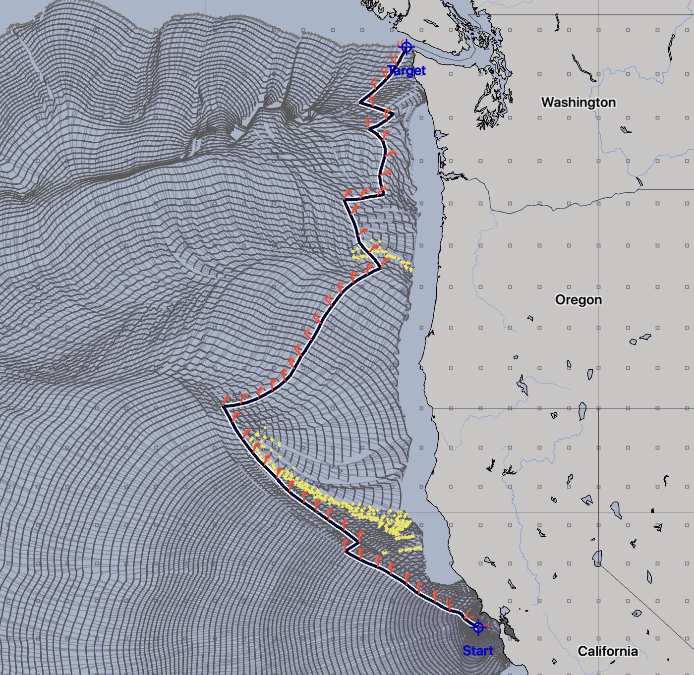
(Click on any of the images for a larger version.)
You can see that as you limit the solver to wider and wider tacking angles, the generated paths can change quite a lot. The duration of these three paths are 7 days 9 hours, 8 days 7 hours and 10 days 7 hours. Any of these may be the best match for your passage, depending on what the actual upwind limit for the vessel is, at the time.
One last example. In this case, we’re showing a sailor who is enjoying downwind sailing in the tropics. The upwind sailing limit is set to 70° apparent, indicating that they do not want to sail higher than a beam reach:
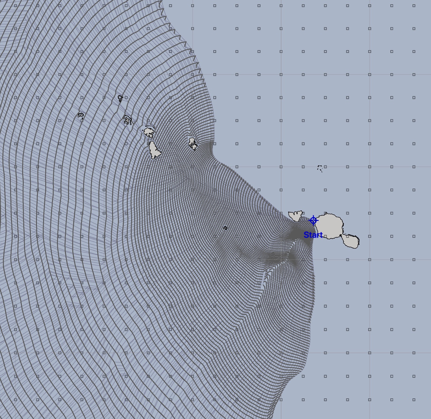
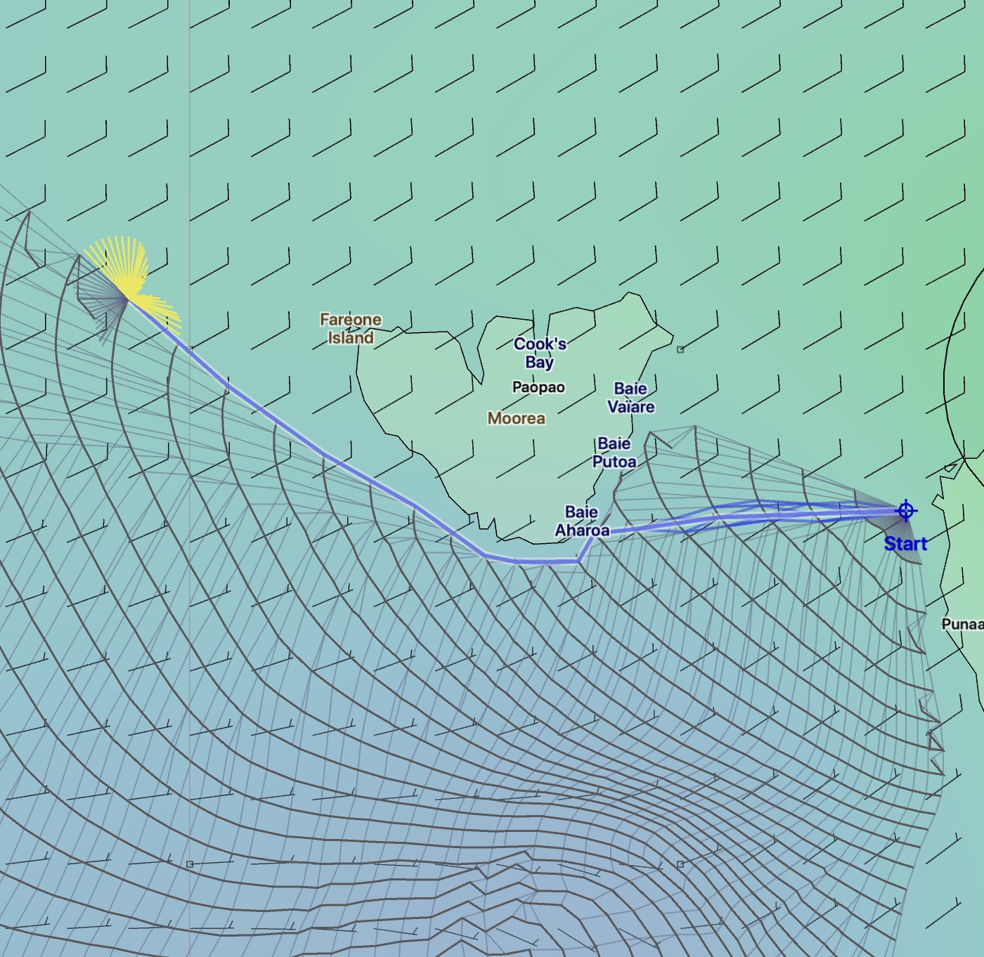
Note that there are now regions the solver is not able to cover. The winds at the start of this solution are generally NE, and so leaving Tahiti, this boat is not able to sail north of Moorea while at the same time, respecting the upwind sailing angle limit.
In the second image, the cursor has been placed near the edge of the isochrone boundary and the cursor fleet is showing the solvers data. All of the yellow headings violate the upwind sailing limit that has been set. The winds shown in that image are valid for the time at the cursor.